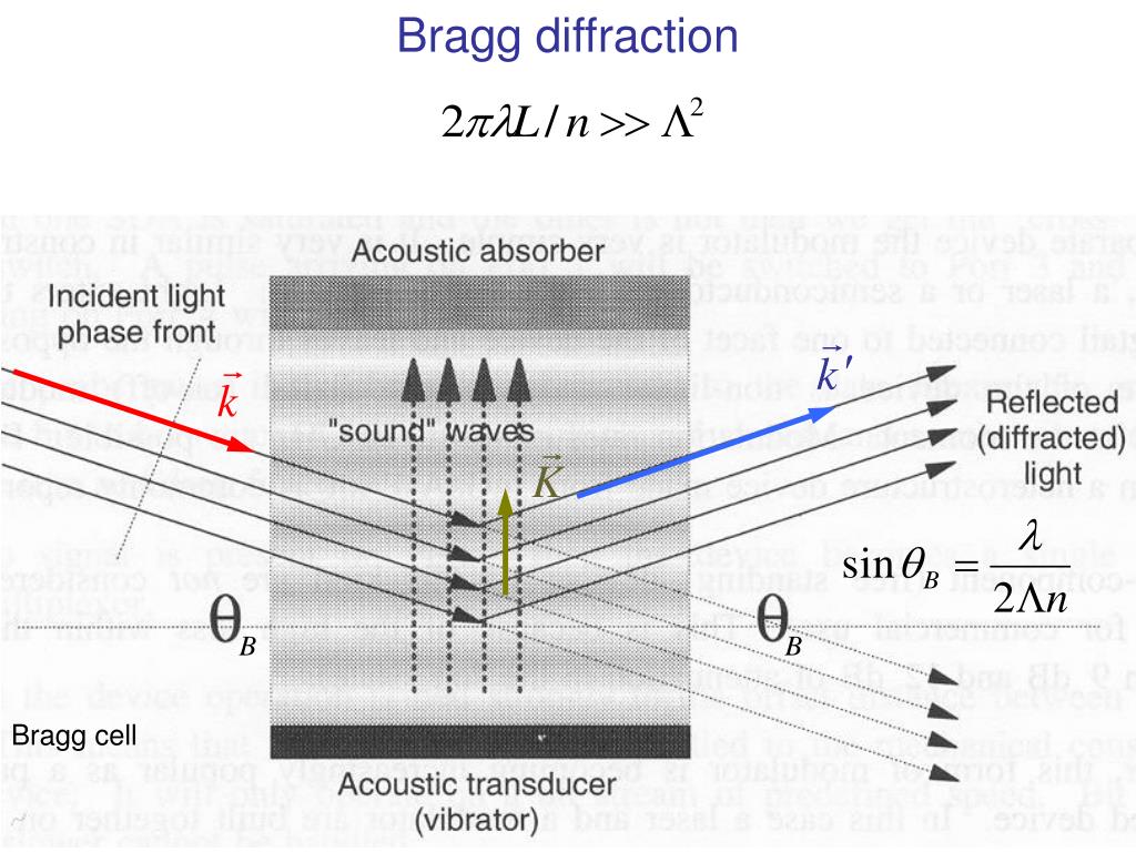

The goniometer is positioned solely by means of electric stepper motors. When switching the X-ray apparatus on, check whether the ventilator in the tube chamber starts rotating.Protect the X-ray apparatus against access by unauthorized persons.Īvoid overheating of the anode in the X-ray tube.Before putting the X-ray apparatus into operation, inspect it for damage and check whether the voltage is switched off when the sliding doors are opened (See instruction sheet of the X-ray apparatus).The built-in protective and shielding fixtures reduce the dose rate outside the X-ray apparatus to less than 1 µSv/h, which is of the order of magnitude of the natural background radiation. The X-ray apparatus fulfils all regulations on the design of an X-ray apparatus and fully protected device for instructional use and is type approved for school use in Germany (BfS 05/07 V/Sch RöV or NW 807 / 97 Rö). Open topic with navigation Energy dispersive Bragg reflection into different orders of diffractionĬan also be carried out with Mobile-CASSY 2 and Pocket-CASSY If you let book author know once you have cited this book, the brief information of your publication will appear on the “Times Cited” page.Energy dispersive Bragg reflection into different orders of diffraction The book author ( Yougui Liao) welcomes your comments, suggestions, and corrections, please click here for submission. Digital Micrograph scripts to compute reflection angles of crystals. Iv) Determine the Burgers vector of lattice defects. Iii) Observe diffraction contrast of lattice defects with certain Bragg reflections or known orientation. I) Observe lattice fringes and crystal structures. Crystalline specimens have to be tilted in a goniometer in TEM in order to: In actual experiments, different from diffuse scattering, the Bragg peaks come from the long-range ordered structure. Bragg angles at various beam voltages for typical d-spacing. The Bragg angles were obtained with Equation 3882b (for n = 1). Table 3882b lists some examples of Bragg angles at various beam voltages for typical d-spacing. Rutherford scattering phonon scattering (< 1 eV, heat) Plasmon excitation (< 50 eV, ~100 nm TEM specimen) Cerenkov effect Effects of interactions of electrons in solids.Įlectron Compton effect electron excitation (from 50 eV to a few keV: EDS and EELS) The angle between incident and reflected waves is equal to 2θ B as shown in Figure 3882. Very strong intensities known as Bragg peaks are obtained in the diffraction pattern when scattered waves satisfy the Bragg condition. widely used to explain electron and X-ray diffraction phenomena. The Bragg angle θ B is a very important concept in diffraction theory, e.g. Λ - The wavelength of the charged particle or electromagnetic radiation waves Īngle between the incident wave vector and the Therefore, we can obtain the well-known Bragg’s diffraction condition, given by, Assuming the hkl planes are spaced a distance d hkl apart and the wave is incident and reflected at angles θ B, both AB and BC are equal to dsin(θ B) and the total path difference should be equal to 2dsin(θ B). Therefore, the path difference between electron waves reflected from the upper and lower planes in Figure 3882 is equal to the total length (AO+BO). The scattered waves interfere constructively if they remain in phase.

The waves reflected off adjacent scattering centers must have a path difference equal to an integral number of wavelengths. In the classic diffraction theory, Bragg diffraction occurs when charged particle or electromagnetic radiation waves with a wavelength comparable to atomic spacing are incident to a crystalline sample. This book (Practical Electron Microscopy and Database) is a reference for TEM and SEM students, operators, engineers, technicians, managers, and researchers.


 0 kommentar(er)
